
Let it glow! - Dynamically adding outlines to characters
Hello everyone,
I'm Micha, aka "Germanunkol". I recently took a course at university on image manipulation and was thrilled by the possibilities - fourier and hugh transformations, filters, noise - there are so many ways to make graphics look better. At the same time, so few Löve projects use shaders - and I want to contribute to changing that.
I decided to try implementing some of the algorithms in Löve and noticed that many of them were quite simple to write and made for great effects in a game.
So this article aims to do two things:
- The first part will give an introduction to some outline-filters and some of the maths behind them.
- The second part is more of a tutorial on how to actually create an outline shader, with the goal to get people deeper into shader programming.
- If you want to skip it all, you can download the final example from here.
For the second part you should have some basic experience with Löve and Lua. Having used a shader before won't hurt either. I will try to cover everything you need to know about shaders in this post, but your reading the introduction to shaders would be a good thing as well.
I go into a lot of detail - but don't be scared off! The final shader is relatively simple and very short.
So let's get started!
Outlines? Outlines!
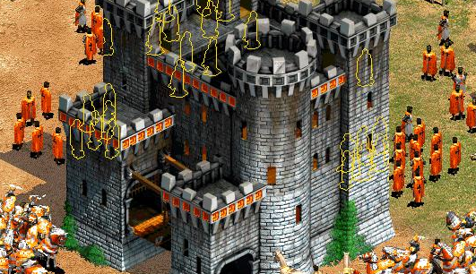
Remember when Age Of Empires II introduced unit-outlines? It was one of those great new features - being able to see your units when they're behind buildings, or behind other units.
But there's other great uses for outlines as well: You could display an outline when the mouse is hovering over a unit, showing that the player can now select this unit. Or display an outline to highlight an important UI feature. Or you could outline a power-up when the player gets close to it. You could even use it to create a hit-effect for your space ship - the number of possibilities is endless.
So how could we go about creating outlines?
The first method that might come to mind is what I'd like to call the "traditional" way:
- Fire up the GIMP, open your "skeleton.png" spritesheet or similar (which should have an alpha channel), duplicate the layer.
- Add a blur to one layer: (Filters->Blur->Gaussian Blur - choose a blur size of 5 by 5 pixels and blur the layer)
- Change the color: With the blurred layer selected, go to Colors->Curves. Play with the red, green and blue channels until you have the color you'd like for your outline. Then go to the alpha channel and increase alpha in the middle range (see image below).
- Move the outline layer below your normal layer and you have an outline!
- Save as "skeleton_outline.png"

This is neat and pretty fast. But there are major disadvantages:
- You'll need to do this for every image which you want to have an outline
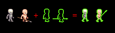
- "Combining" outlines will never work this way. For example: If you give the skeleton a weapon (or a bunch of flowers, for that matter), the attached object's oultine will cover parts of the skeleton - instead, what I'd like is a combined outline for the two.
- Changing color for the outline dynamically only works if you store it in a seperate image.
- Growing/Blinking/fading of the outline won't work.
So - the traditional method won't cut it. Let's use shaders instead!
Part 1. The Theory
First of all: What is an outline, really? Drawing a rectangle around a rectangular image is trivial in Löve. That's not what we want to do. Instead, we want to highlight the area where there's a transition from "transparent" to "non-transparent". This area can have all kinds of shapes and will very rarely resemble a primitive which we can draw using the love.graphics functions.
Since we want to highlight the changes of the transparency (or alpha value), we'll ignore the red, green and blue channels for now - changes in color should not affect our outline.*
* Using the filters on the color channels can have some neat effects as well, try it!
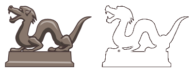
Now, to get these "changes in alpha", consider the following image:

The left image shows some object being drawn on the screen. If we move from left to right through the image, following the red line, and note down the alpha value of every pixel we pass, then we get the plot on the right - the alpha is first 0 (transparent) and then jumps to a high value, stays at that high value while we're moving through the image and then falls back down to zero. There's two areas where the function on the right changes - these are the two areas we're interested in. Now, remember how to get the changes in a function? Exactly - we simply need to calculate the derivative:

The plot on the right shows the derivative. It's zero where there are no changes in the function and non-zero where there are changes - just what we wanted.
When working with images, we only have descrete coordinates, so we don't need to worry about actually calculating the derivative. Instead, there's a neat trick:
For every pixel, take the alpha value of the pixel to the right and subtract from it the alpha value of the pixel to the left. Consider these two examples:

In the left image, subtracting the alpha value at 9 from the alpha value at 11 yields (1-0) = 1. In the right image, (1-1) = 0. So we have a high value (1) when there's a change and a low value (0) when the alpha stays the same.
The next thing we'll do is represent this equation as a filter kernel.
Kernels
A kernel is a grid, or matrix of (often 3x3) values. It is used when doing a convolution over the image.
To calculate the convolution, you place the kernel onto the image and line it up with the pixels. Then you multiply the values which the pixels hold (in our case, only the alpha values are considered, but others can be used as well) by the values written in the kernel entries right above them, and add the results together:

Green is the pixel we're currently looking at. The filter-kernel has an entry for each pixel surrounding our current pixel, and for the current pixel as well - so 9 altogether. For the simple derivative, we'll only need two entries, the ones to the left and the right of the current pixel. All the others will be set to zero.
Each entry in the kernel tells us by how much we need to multiply the corresponding pixel before we add the results together - in our case we need to multiply the left and right neighbouring pixels by -1 and 1, respectively, and then add them together.
Let's try this in the GIMP.
- Open up the GIMP, load any image file you want to process (make sure it has an alpha channel).
- Go to Filters->Generic->Convolution Matrix. If you enter our kernel into the pop up, you'll get the derivative (in horizontal direction) of the image. Make sure only the alpha channel is checked to get the same results as I do.

Result:
There is a horizontal and a vertical version for this filter:

These kernels are often used to get to the so-called "Sobel Filter" for edge detection. All we need to do is blur this matrix, which I might explain in another post one day.
While this filter works, there's are a few drawbacks...
You'll notice that only the edges on the left side are being shown. That's something I didn't mention before: If you go back to the above image of the alpha-function, you'll notice that at the right edge, when applying our formula, you'll get (0-1) = -1. Since this value is negative, the GIMP will ignore it (or clamp it to zero). This can be fixed by simply taking the absolute value of the derivative instead:

However, even when having done that we still don't have any of the edges in vertical direction - and this is where this method fails. The only way to fix this is to also calculate the derivative in y direction and then add the two together.
There is, however, a better method: The Laplace-Filter
Before, we calculated the derivative, a'(x). Now, we'll consider the second derivative instead, a''(x). This looks approximately like this:

(A note of caution here: Our original function was piecewise linear. Off course this means that the second derivative is technically zero throughout the whole image, with the exception of a few infinitifely high spikes where there are jumps in the derivative. However, the way we're calculating it makes the whole principle work, because of the way we're approximating it.)
The Laplacian can be approximated by using the kernels (horizontal and vertical again):

To get the final Laplacian, we'll add the two kernels together into one. This results in the image on the left here. There's another approximation which is commonly used, which also takes into account the diagonal values, that's the kernel on the right:

Trying both of these in the GIMP again gives us some nice results:
This looks good. So this will be the filter we'll use.
Enough theory, let's get coding...
Part 2: The Shader
Tutorial Framework
To speed things up, I've created a quick n' dirty tutorial framework. It creates two animated characters and lets them walk in an endless loop.
Download the framework from here.
Alternatively, you can also clone the repository on your command line using:
git clone https://github.com/Germanunkol/ShaderTutorialFramework.git
The Shader:
We'll need a new file called "outline.glsl". Create the file in the same folder as main.lua.
Into this file, put the following code:
vec4 effect( vec4 col, Image texture, vec2 texturePos, vec2 screenPos )
{
    // simply return the color at the current coordinates:
    return texture2D( texture, texturePos );
}
Short explanation:
Whenever the shader is active, the "effect" function will be called once for every pixel which is drawn. So if we draw a 32x32 pixel image, it'll run for each of the 32*32 = 1024 pixels.
The "col" argument gives us the currently set color, which we won't need for this shader.
The second argument is the image being drawn.
The third argument holds the coordinates for the pixel we're currently drawing - in texture-space (i.e. "Which pixel of the texture are we drawing"), ranging from 0 to 1.
The last argument holds the coordinates of the pixel on the screen (i.e. "Where on the screen are we drawing the pixel") - again something we won't need for this shader.
Inside the function, all we do for now is a texture-lookup: texture2D is a function that simply returns the color of the pixel in the given texture, at the given coordinates. So the shader does not modify anything at the moment - it simply draws the image.
To make sure it's all working, though, let's try setting the shader:
Open up character.lua and add this to the Character:new() function (before the "return o"):
o.shader = love.graphics.newShader( "outline.glsl" )
This creates a new shader for every character which is created.**
Go down to Character:draw() and modify it to look like this:
function Character:draw()
    love.graphics.setShader( self.shader )
    love.graphics.draw( self.img, quads[self.frame], self.x, self.y )
    love.graphics.setShader()
end
This enabled the shader before drawing the character, and disables the shader again after drawing it.
Run the project (using "love ." or similar) to test if it's working. You should see two characters walking side by side.
** This is probably not an ideal solution if you have loads and loads of characters or units. In that case, you should create only one shader, globally, and then re-use it whenever you need it. That's not really more difficult, but if you want to assign custom values to the shader for your different units (green outlines for friendly units, red for enemies and blue for drunk skeletons?) you'll need to send them every frame before using the shader - that's why I didn't choose this method here.
To see if the shader is working, modify your outline.glsl to this:
vec4 resultCol;
vec4 textureCol;

vec4 effect( vec4 col, Image texture, vec2 texturePos, vec2 screenPos )
{
    textureCol = texture2D( texture, texturePos );
    resultCol = vec4( 1.0f, 1.0f, 1.0f, textureCol.a );
    return resultCol;
}
We perform the texture lookup as before, but then instead of returning that color, we return a modified color where the red, green and blue channels are set to white and only the alpha channel is perserved (textureCol.a gives the alpha of the textureCol color, textureCol.r would give the red value and so on). Run the code - what you should see now is the two characters walking, but they should be plain white. That's what the 1.0, 1.0, 1.0 does.
Now let's create the outline!
The outline should be composed of two things:
- The alpha of the outline (i.e. where it is showing) should be given by the second derivative (more precisely the laplacian) of the input image.
- The color of the outline should be a fixed color for now.
Let's focus on the first point for now.
Remember, what we need to do is: For every pixel we add together the alpha of the 4 nearest surrounding pixels. Then we subtract the result from 4 times the alpha of the current pixel.
The math is simple. Imagine the function alpha(x, y) can get the alpha of the pixel which is found at an offset of x and y from the current pixel (alpha(0,0) being the alpha of the current pixel) then we can calculate the new alpha as:
alpha = 4*alpha(0,0) - ( alpha(-1,0) + alpha(0,-1) + alpha(1,0) + alpha(0,1) )
In GLSL, we can do this by adding to the texture coordinates, before we do the texture-lookup:
...
{
    number alpha = 4*texture2D( texture, texturePos ).a;
    alpha -= texture2D( texture, texturePos + vec2( 0.001f, 0.0f ) ).a;
    alpha -= texture2D( texture, texturePos + vec2( -0.001f, 0.0f ) ).a;
    alpha -= texture2D( texture, texturePos + vec2( 0.0f, 0.001f ) ).a;
    alpha -= texture2D( texture, texturePos + vec2( 0.0f, -0.001f ) ).a;
Note that we're adding small values like 0.001 to the position for now - this is because the texturePos values range from 0 to 1 (not from 0 to 64 as in our image). If we'd add 1 (or subtract 1, for that matter), we'd move the coordinates not by one pixel, but by the width of the whole image!
Now let's calculate the final color:
    // calculate resulting color
    resultCol = vec4( 1.0f, 1.0f, 1.0f, alpha );
    // return color for current pixel
    return resultCol;
}
...
If we run the game now, we'll see our first outline - hooray!

However if you look closely, you'll see that the outline is a bit thicker at the top and bottom than it is at the right and left - why is that?
Well, to get the coordinates of the "neighbouring pixels", we used a very naive approach: we just added "0.001" to the coordinates, both in x and y direction. Since these are texture coordinates, what that means is "go 0.001 of the image width into the x direction and 0.001 of the image height into the y direction". Since image width and image height of the spritesheet image we're using are not the same (open up skeleton_3.png and you'll see), we're actually moving further up and down than right and left when we try to get "neighbouring" pixels. This effect would be even more noticable if the width and height of our image went more into the extreme - a 20x400 image, for example, would not look good any more.
Instead, we should try to go exactly one pixel left and right.
To do that, let's add a new variable, called "stepSize". This variable will tell us how much we should go left and right, or up and down, in order to move by exactly one pixel. Since we need two different values for horizontal or vertical movement, we make it a "vec2", which holds two values. Add this line at the beginning of the shader (outside the effect funtion):
extern vec2 stepSize;
We add the keyword "extern" to make sure this variable can be modified from within our Lua code.
Now, instead of the previous fixed value of 0.001, let's use stepSize in our code:
    number alpha = 4*texture2D( texture, texturePos ).a;
    alpha -= texture2D( texture, texturePos + vec2( stepSize.x, 0.0f ) ).a;
    alpha -= texture2D( texture, texturePos + vec2( -stepSize.x, 0.0f ) ).a;
    alpha -= texture2D( texture, texturePos + vec2( 0.0f, stepSize.y ) ).a;
    alpha -= texture2D( texture, texturePos + vec2( 0.0f, -stepSize.y ) ).a;
But how do we calculate the correct step size?
Open up characters.lua again, and jump, once again, to the Character:new() function. After the creation of the shader, add this line:
o.shader:send( "stepSize",{1/o.img:getWidth(),1/o.img:getHeight()} )
What we do is: We send two values to the "stepSize" variable of the shader. By using 1/width and 1/height, we get exactly distance between two pixels. (If you're confused by that, think of is this way: If the image is 4 pixels wide and 4 pixels high, then stepSize will now hold the values {1/4, 1/4}, or {0.25, 0.25}. Now imagine we're running the effect function for the pixel 1,2. In the effect function, the texturePos variable will now hold {0.25, 0.5}. So adding and subtracting the value 0.25 from it, we'll get the coordinates shown in the following picture:

These are exactly the neighbouring pixels which we want. So the 1/width, 1/height thing did just what we wanted - it calculated the distance in horizontal and vertical direction between pixels in GLSL's texture coordinates.)
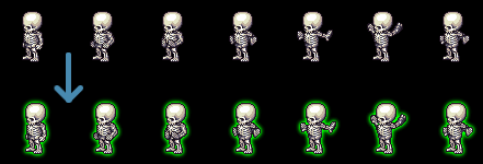
Now run the program again - and voilà, we have a pretty outline!
Making it prettier:
To change the color of the outline, you can try changing the line which calculates the resultCol to something like:
resultCol = vec4( 0.2f, 1.0f, 0.1f, alpha );
To add the outline ontop of the original image, simply draw the image twice, once without and once with outline shader applied:
function Character:draw()
    love.graphics.draw( self.img, quads[self.frame], self.x, self.y )
    love.graphics.setShader( self.shader )
    love.graphics.draw( self.img, quads[self.frame], self.x, self.y )
    love.graphics.setShader()
end
And, most importantly: To make it thicker, play with the stepSize values. Higher values create thicker lines:
o.shader:send( "stepSize",{3/o.img:getWidth(),3/o.img:getHeight()} )
Closing remarks:
- You can download the final example here.
- If you want to display the outline even when the character is behind a wall or similar, simply draw the character first (without shader applied), then draw the walls and then draw the outlines above the walls.
- We can make the outline shader even prettier if we blur the image using a shader before rendering the outline, or if we blur the outline after creation. I'll leave both of these methods for a possible future blog post, though.
- If you have any questions or comments, feel free to write me a pm in the forums.
Sobel filter:
For completeness' sake, here's the approach mentioned above, using the plain derivative (in horizontal direction - it can easily be modified to the vertical direction). Here, no blur is being applied, but you can add that as well by using the Sobel filter kernels above.
vec4 resultCol;
extern number stepSize;

number alpha;

vec4 effect( vec4 col, Image texture, vec2 texturePos, vec2 screenPos )
{
    // get color of pixels:
    alpha = texture2D( texture, texturePos + vec2(0,-stepSize)).a;
    alpha -= texture2D( texture, texturePos + vec2(0,stepSize) ).a;

    // calculate resulting color
    resultCol = vec4( 1.0f, 1.0f, 1.0f, 0.5f*alpha );
    // return color for current pixel
    return resultCol;
}
The skeleton and spearman images used in this post come from OpenGameArt.org and are licensed under the creative commons license. See the following link for authors and copyright information. Thanks to the authors for making these accesible!
Comments
nickm50
Sun, 04/27/2014 - 00:53
Permalink
Thank you Micha, this was very helpful. Are you still planning on posting the second part where you talk about using blur?
Germanunkol
Mon, 04/28/2014 - 13:41
Permalink
Hi,
Yes, I'd still like to write an article on that.
I'm pretty busy at the moment, but I'll probably get around to it next month. Thanks for letting me know there's interest!
Is there anything you're specifically interested in? Blurring the outlines, or just blurring a full image, or anything else?
Splatpope
Wed, 05/07/2014 - 08:59
Permalink
For what concerns me, I'd be interested in not only blurring, but also other pixel shading methods.
I myself have dabbled with linear interpolation in Processing, never achieving any good results and I'd love to try my hand at all those wonderful image manipulation methods in LÖVE :D
Germanunkol
Tue, 05/13/2014 - 15:49
Permalink
Great to hear interest.
I'll see what I can do!
It's always difficult to find the line between theory and code/application here, i.e. explain what's going on without going too much in depth. But I'll try!
Chron
Mon, 06/09/2014 - 16:21
Permalink
When you listed the flaws of simply generating the outlines in GIMP, you mentioned:
But how is this solved with the Shader? Is there some way to "combine" two images and apply the shader to this combination?
Germanunkol
Fri, 06/20/2014 - 02:38
Permalink
Hi!
Yes, actually, there is.
It's not quite as simple as I made it sound, but you can render both images to a canvas, then activate the shader and render the canvas onto the actual screen. Something like this (untested):
love.graphics.setCanvas( myCanvas ) -- start rendering to canvas. need to create myCanvas before (in love.load, for example)
love.graphics.draw(skeleton, 0, 0 )
love.graphics.draw(flowers, 0, 10)
love.graphics.setCanvas() -- stop rendering to canvas
love.graphics.setShader(theOutlineShader)
love.graphics.draw(myCanvas, skeletonX, skeletonY)
Chron
Sat, 06/21/2014 - 16:31
Permalink
Thanks for the reply! I just tested this with my code, but I'm running into a problem: I have a function that draws my player, which I execute within love.draw(). However, I'm also using a camera and love.graphics.scale(). Now, since my player:draw() (which now draws onto the player canvas, and then draws the canvas) is executed with camera and scaling applied, those are applied twice (once when drawing onto the canvas, and again when drawing the canvas itself).
I know this could be solved by first drawing onto the canvas outside of camera and scaling, and then drawing the canvas with camera and scaling applied, but I'd prefer to stick with only having to use one function for drawing. Is that somehow possible?
I also have another question, if that's okay: When drawing my player, I offset the image so that the x-Coordinate is at the center of the player (I do that for rotation to work properly). However, when I draw the canvas, only the right half (the positive coordinates) are drawn. How do I draw the pixels with negative coordinates in a canvas?
Germanunkol
Sat, 06/28/2014 - 02:35
Permalink
Hi!
Sorry, I don't get notified when there's a new message here. If getting a quicker answer in the future is important to you, maybe try writing a pm on the forums, or open a thread there.
To your first question:
I know the issue, it's really annoying. Two solutions come to mind: If your camera is a global variable, call the cam:clear (or similar) function on it from within the player function, before drawing onto the canvas. Afterwards, before drawing the canvas onto the screen, re-call the cam:apply() (or whatever it's called in your code) again. This way the camera settings only get applied when drawing the result of the canvas.
Another, maybe prettier version is this (untested): When you want to draw to the canvas, do a love.graphics.push() followed by a love.graphics.origin(), which should also reset the coordinate system for the following draw call. Then call love.graphics.pop() again after drawing onto the canvas (before drawing the canvas onto the screen).
Also: Make sure the canvas is only as large as it needs to be - I believe making it larger wastes resources. So only make it as large as the player, then draw the player at 0,0 into the canvas and draw the canvas onto the screen at the actual player position. I also recommend only rotating the canvas (not the player), because then you only need to worry about rotation once - otherwise you'll need to rotate every element you draw onto the canvas.
If this doesn't solve your rotation problem, I'd have to see some code... it sounds like the canvas isn't large enough - so as said above, make it just as large as the player's image (plus any size needed for the objects you want to attach to it) and then draw the player in the upper left corner of the canvas. Then move and rotate the canvas when drawing it.